| 1 |
Calculate the electrical load |
Determine the wattage of all appliances and equipment that may operate on the circuit. |
Use the formula Amps = Watts ÷ Volts. For example, a 1,500-watt load on a 120-volt circuit draws approximately 12.5 amps. |
Do not size the wire only by the number of outlets. The expected load and applicable electrical code determine the required circuit capacity. |
| 2 |
Match the wire to the circuit rating |
Identify the circuit-breaker or fuse rating, such as 15, 20, or 30 amps. |
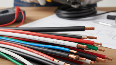
Common copper branch-circuit examples include 14 AWG for 15-amp circuits, 12 AWG for 20-amp circuits, and 10 AWG for 30-amp circuits, subject to installation conditions and local code. |
Never install a larger-rated breaker simply because a larger wire was used. The breaker must protect the entire circuit and connected equipment. |
| 3 |
Check the system voltage |
Confirm whether the circuit operates at 120 volts, 240 volts, or another voltage permitted by the local electrical system. |
Many lighting and receptacle circuits use 120 volts, while some ranges, dryers, water heaters, and heating equipment use 240 volts. |
Voltage affects current, conductor arrangement, breaker configuration, and equipment compatibility. Verify the appliance nameplate before wiring. |
| 4 |
Consider continuous loads |
Identify equipment expected to run for three hours or more, such as lighting systems, pumps, or ventilation equipment. |
Under common electrical-code practice, continuous loads are often calculated at 125% of their rated current when sizing the circuit. |
Apply the rules required in your jurisdiction. A qualified electrician should verify the calculation for fixed or high-power equipment. |
| 5 |
Account for wire length and voltage drop |
Measure the one-way distance from the panel to the load and estimate the operating current. |
Long runs may require a larger conductor to limit voltage drop. A commonly used design target is about 3% on a branch circuit and 5% for the feeder-plus-branch-circuit system. |
Voltage-drop guidance may differ by code and application. Motors and sensitive electronics can be especially affected by low voltage. |
| 6 |
Select the correct conductor material |
Choose between copper and aluminum conductors based on the equipment, terminals, size, and installation requirements. |
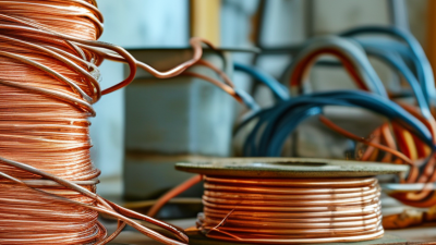
Copper generally has higher conductivity for the same cross-sectional area. Aluminum conductors can be suitable for certain larger feeders when listed equipment and approved terminations are used. |
Do not place aluminum conductors under terminals that are not identified for aluminum. Follow the terminal markings and approved connection methods. |
| 7 |
Verify ampacity and temperature ratings |
Check conductor ampacity, insulation temperature rating, ambient temperature, and the rating of connected terminals. |
Although some insulation is marked 90°C for adjustment calculations, the final allowable ampacity may be limited by 60°C or 75°C equipment terminals and other code conditions. |
Conductor ampacity must also be adjusted for high ambient temperatures and multiple current-carrying conductors in the same raceway or cable. |
| 8 |
Choose the appropriate cable or wiring method |
Determine whether the wiring is inside a finished wall, exposed, underground, outdoors, or in a damp or wet location. |
Common options include sheathed cable for approved dry interior locations, individual conductors in raceway, and conductors specifically listed for wet or outdoor locations. |
Use only wiring methods permitted for the location. Indoor cable is not automatically suitable for sunlight, burial, conduit outdoors, or wet areas. |
| 9 |
Include grounding and neutral conductors |
Identify the required ungrounded conductors, grounded neutral conductor, and equipment grounding conductor. |
A typical 120-volt branch circuit requires a hot conductor, a neutral where needed, and an equipment grounding path. A 240-volt circuit may or may not require a neutral depending on the load. |
Never use a neutral conductor as a substitute for the equipment grounding conductor. Maintain correct conductor identification throughout the installation. |
| 10 |
Check protection and local requirements |
Determine whether the circuit requires ground-fault or arc-fault protection, dedicated equipment, disconnects, or special receptacles. |
Many residential areas require GFCI protection in locations exposed to moisture and AFCI protection in specified living areas. Requirements vary by jurisdiction and circuit type. |
Obtain the required permits and inspection where applicable. Turn off power, verify the circuit is de-energized, and consult a licensed electrician for new or modified wiring. |