Leave Your Message

How to Choose the Right Cable Supports for Your Project

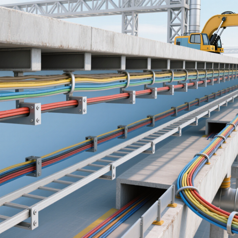
Choosing the right Cable Supports begins with understanding what the installation must carry, where it will run, and how it may change over time. A tray beneath a concrete ceiling faces different demands from supports beside vibrating machinery or exposed to weather. Cable weight matters. So do span length, bend radius, access for maintenance, and the environment around each fixing point.

A useful design principle is: “Choose supports for the cables you will install—and the conditions they will face.” This is an editorially written maxim, not a verified quotation from a named expert; no source was provided for an authentic expert quote. For a published article, add a named specialist’s words only after verifying their identity and exact quotation.

Small details can carry real consequences. Picture a long cable run above a busy service corridor: a support spaced too far apart may allow sagging, while an unsuitable material may corrode in a damp area. The right choice balances load capacity, material, spacing, installation method, and future access. It also follows the project’s applicable specifications and manufacturer guidance. A tidy drawing is not enough. Assumptions deserve a second look, especially when cable loads or site conditions are uncertain.

This guide explains how to compare common support types, check practical requirements, and avoid choices that make installation or maintenance harder. The best solution is not always the largest or most expensive one. It is the one suited to the actual route, load, and working environment.

How to Choose the Right Cable Supports for Your Project

Understanding Cable Supports and Their Role in a Project

Cable supports do more than hold wires in place. They control sag, protect insulation from sharp edges, and keep routes accessible for inspection. A stable run also reduces strain at bends, junctions, and equipment entries. Small detail. Big consequence. NFPA’s Electrical Fires report estimated an average of 31,647 U.S. home structure fires involving electrical distribution and lighting equipment each year from 2015 to 2019. That figure does not isolate cable supports, but it shows why sound electrical installation deserves careful attention.

Choose supports by cable weight, span, temperature, moisture, and exposure to vibration or impact. A ladder tray may suit heavy runs; a closed tray can help shield cables from dust or falling debris. Check the project specification and the relevant installation guidance, including IEC 61537 for cable tray and ladder systems. On site, verify the actual support spacing against cable and system requirements; assumptions made from a drawing can miss real loads. And, honestly, future access is often the part teams underthink. Leave room for inspection and later cable additions, even if the route looks less tidy.

How to Choose the Right Cable Supports for Your Project - Understanding Cable Supports and Their Role in a Project

Cable supports carry and organize electrical or data cables, help maintain routing, and reduce strain on cables and connections. The best option depends on cable type, route, environment, access needs, support spacing, and applicable project requirements.

Support Type Typical Applications Key Benefits Selection Considerations Common Materials Project Check
Cable tray Grouped power, control, or communications cables along corridors, ceilings, and industrial routes. Provides an organized pathway and allows access for inspection and cable additions. Choose tray type and size based on cable quantity, weight, route, environment, and required separation. Steel, stainless steel, or aluminum; finish depends on the environment. Confirm support locations, loading, bonding requirements, and installation clearances against the project design.
Ladder tray Long runs of heavier cables, often in industrial or utility areas. Open construction supports ventilation and makes cable routing and inspection accessible. Check cable support requirements, span limits, fittings, and exposure to debris or impact. Steel, stainless steel, or aluminum. Use the manufacturer’s load and span data and the applicable electrical installation rules.
Wire-mesh basket tray Light-to-moderate data, communications, and low-voltage cable routes, particularly where routes change frequently. Lightweight, open, and adaptable; cables are easy to access and add. Assess cable weight, required support spacing, edge protection, and suitability for the installation environment. Typically steel with a protective finish; other finishes may be available. Check that cut ends and fittings are finished appropriately and that the system is securely supported.
Conduit with straps or clamps Individual or small groups of cables requiring a defined, enclosed route. Provides physical protection and a contained pathway; useful where cables need protection from contact or exposure. Consider conduit fill, bend requirements, access points, corrosion exposure, and cable pulling needs. Metallic or nonmetallic conduit and compatible fittings. Use fittings and supports suitable for the conduit type and installation conditions.
Cable cleats Securing individual or grouped cables to a structure, often on vertical runs or where movement must be controlled. Helps restrain cables and maintain their position when correctly selected and installed. Match the cleat to cable size, grouping, installation conditions, and any required short-circuit restraint performance. Metallic or nonmetallic materials, selected for the application. For fault-current restraint, use verified system data and qualified electrical design guidance.
J-hooks or cable hooks Supporting communication and other suitable lightweight cables above ceilings or along open routes. Quick to install and provides an accessible route without enclosing the cable. Check cable compatibility, bundle size, support spacing, bend radius, and whether the location requires a rated pathway. Metal or polymer, depending on the product and application. Avoid overfilling and sharp edges; follow cable and support manufacturers’ installation guidance.
Strut channel and trapeze supports Suspending trays, conduits, or multiple cable pathways from building structure. Flexible arrangement for supporting one or more services across a shared route. Account for total supported load, anchor type, span, vibration, and the condition of the supporting structure. Usually steel; corrosion-resistant options are available. Verify the complete assembly, including anchors and attachments, for the project’s design loads.

Selection reminder: Confirm cable weights, support spacing, allowable loading, environmental exposure, fire and building requirements, and electrical code requirements for the project location. Actual capacities and spacing vary by product, installation method, and loading; use manufacturer documentation and the approved project design.

Identifying Cable Types, Routes, and Support Requirements

Cable support selection starts with the cable itself. Separate heavy power cables, lightweight control wires, and fiber-optic lines. Check each cable’s weight, outside diameter, bend radius, and temperature rating. A thick feeder cable needs a different support profile than a flexible data cable. Leave room for future additions; crowded trays make inspection harder.

Next, map the route and its conditions. Note ceiling drops, sharp turns, vibration, moisture, and access points. IEC 61537:2023 evaluates cable tray systems using safe working loads and defined support spans. That matters: there is no universal spacing rule for every tray and cable load. Confirm the manufacturer’s load tables, then verify the actual span and combined cable weight. I still see route plans that overlook one short offset. It can shift the load.

Tips: Mark cable groups and route changes on the drawing. Use supports rated for the environment, and keep bend radii visible at corners. Don’t tighten ties until the cables sit naturally. A neat run is useful, but service access matters more. Before installation, compare field measurements with the plan; one beam or pipe can change the support layout.

Comparing Support Materials and Designs for Site Conditions

Site conditions should guide both support material and design. Galvanized steel suits many dry indoor routes and offers a practical balance of strength and cost. In coastal air or washdown areas, stainless steel resists corrosion better, though its added cost may not be necessary everywhere. Aluminum is lighter and useful where handling weight matters, but check its load rating before specifying it for long spans. For damp interiors, polymer supports can avoid rust, yet heat, sunlight, and cable weight may limit their use. Check coating damage at cut edges. Small scratches matter.

Design changes how cables behave after installation. Ladder-style trays allow airflow and make visual inspection easier, while solid-bottom trays shield cables from falling dust and debris. Individual cleats can restrain cables against movement, but spacing must suit cable size, weight, and expected forces. Allow room for bends and thermal movement near equipment connections. Measure twice. Confirm support spans against rated loads, and consider corrosion where different metals touch. A tidy drawing can miss a drainpipe or a vibrating pump. Walk the route before ordering; field measurements are less neat, but usually more useful.

Sizing Supports for Cable Loads, Spacing, and Future Expansion

Cable support sizing starts with the cables, not the support catalogue. Add the weight of every cable across each span, then consider pulling tension, vibration, and any expected movement. A bundle that looks light on a drawing can become heavy when several runs share one route. Measure twice.

Support spacing depends on cable type, installation direction, and the load limits of the support itself. Flexible cables may sag between supports; heavier or more delicate runs may need closer spacing. Check the cable and support manufacturers’ load tables, and verify that anchors suit the actual wall, ceiling, or structure. There is no single spacing that fits every installation. A short test section can reveal sag or access problems before the full route is installed.

Leave room for planned additions, but do not count unused capacity as permission to exceed rated loads. Reserve space for extra cables and keep bends accessible for inspection. A common design miss is allowing spare capacity on paper while filling every easy-to-reach section during installation. Recheck the load and support spacing if the cable count, route, or operating conditions change. For critical or unusually heavy runs, have a qualified engineer review the design.

Checking Installation, Safety, and Maintenance Requirements

Cable supports should match the route, cable weight, and installation environment. A tray may suit a long, accessible run, while clamps can help secure individual cables near equipment. Check the support’s load rating and spacing instructions before drilling. Then inspect the wall, ceiling, or frame for suitable fixing points. Concrete, thin sheet metal, and timber need different anchors. Small detail. Keep cables clear of sharp edges and hot surfaces, and allow enough room for bends and future access. A layout that looks tidy on paper may become awkward around beams or crowded junctions; a site check can catch that.

During installation, confirm that supports sit firmly and do not pinch or deform cable jackets. Use suitable tools, and follow the cable and support specifications rather than guessing at spacing. Where work is near energized systems, arrange safe isolation and have qualified personnel handle the task. Requirements vary by system, so confirm them with the responsible project professional. After installation, record support locations and any concealed routes. This is easy to skip, but it can save time later. Maintenance checks should look for loose fixings, corrosion, cracked components, sagging spans, and signs of heat or abrasion. Inspect more often where vibration, moisture, dust, or frequent access may affect the supports. A quick visual check is useful, though it will not reveal every hidden issue.

How to Choose the Right Cable Supports for Your Project

Checking Installation, Safety, and Maintenance Requirements

The bars count the practical checks listed for each project phase in this guide; they are not scores or industry-standard quantities. Confirm support spacing, load limits, materials, and installation details against the project requirements and manufacturer documentation. Consider site conditions and applicable codes, and inspect supports periodically for corrosion, loose fixings, or damage.