Leave Your Message

How to Choose the Right Cable Supports for Your Project

Choosing the right Cable Supports is more than selecting a product from a catalogue. It requires practical judgment, verified data, and a clear understanding of the installation environment. A support system must carry the cable load safely, maintain separation, and remain stable during maintenance. It may also face heat, moisture, vibration, chemicals, or limited access.

Mike Holt, a widely recognized electrical-code educator, puts the principle plainly: “Code compliance is the starting point, not the finish line.” That mindset matters here. Standards establish minimum requirements, but project conditions demand deeper evaluation. A support suitable for a dry indoor corridor may perform poorly beside a cooling tower. Small details matter. Anchor spacing, bend radius, corrosion resistance, and future cable additions can change the correct decision.

This guide explains how to compare Cable Supports by load capacity, material, mounting method, and service environment. It also considers installation time and inspection access. Field experience shows that the cheapest option is not always economical. Rework is expensive. Sometimes, a support selected too quickly creates unexpected sagging, sharp cable bends, or difficult repairs.

No selection is perfect on paper. Assumptions can be wrong. Therefore, engineers and installers should review manufacturer specifications, project drawings, and applicable electrical requirements together. A careful choice protects equipment, reduces maintenance risks, and supports reliable performance throughout the system’s service life.

How to Choose the Right Cable Supports for Your Project

Define Cable Loads with NEC Chapter 9 Tables 1 and 5A

Choosing cable supports starts with accurate load definition. NEC Chapter 9, Table 1 limits conductor fill to 53% for one conductor, 31% for two, and 40% for more than two. These percentages are essential when cables share a raceway, tray, or enclosed support path. The figures come from NFPA 70, 2023 edition, Chapter 9, Table 1.

Table 5A provides conductor dimensions and approximate areas for insulated wires. Use those values to estimate bundle size, surface pressure, and support spacing. A larger cable may look manageable on a short run, yet repeated weight can stress bends, connectors, and mounting points. Measure the actual cable whenever possible. Printed dimensions can differ slightly by insulation type and temperature rating.

Do not confuse fill with weight. Table 1 addresses space, while Table 5A helps calculate occupied area. Neither table alone determines the correct support interval. Manufacturer installation data, project specifications, and applicable local requirements still matter. In field work, I have seen supports selected from diameter alone. That was convenient, but incomplete. Cable weight, grouping, vibration, and future additions deserved closer review. A practical check is simple: calculate the bundle, inspect the bend radius, then verify the support can carry the expected load. “Almost enough” is not a reliable design margin.

How to Choose the Right Cable Supports for Your Project

Define Cable Loads with NEC Chapter 9 Tables 1 and 5A

NEC Chapter 9 Table 1 limits the maximum conductor fill in a raceway to 53% for one conductor, 31% for two conductors, and 40% for three or more conductors. The bars use approximate conductor cross-sectional areas associated with common insulated conductor sizes in Table 5A. Use the calculated total conductor area, the applicable fill limit, and the installation environment to select cable supports with adequate capacity and spacing. These values address physical fill and support planning, not conductor ampacity.

Apply NEC’s 40% Fill Benchmark to Size Support Capacity

How to Choose the Right Cable Supports for Your Project

Apply NEC’s 40% Fill Benchmark to Size Support Capacity

Cable supports must handle more than the cable count. They must support weight, spacing, movement, and installation conditions. In many cable tray layouts, the NEC uses a 40% fill benchmark for multiconductor cables. Treat this value as a planning limit, not a universal rule. The applicable NEC article, cable type, and local inspection requirements still matter.

Measure the inside width and usable depth of the proposed support. Then estimate the cable area and compare it with 40% of that space.

A tray measuring 12 inches wide and 3 inches deep provides 36 square inches of internal area. Forty percent allows about 14.4 square inches for cables. Do not fill the remaining space automatically. Cooling, pulling access, and future additions need room.

Weight is equally important. Add the cable weights per foot, then multiply by the support span. Include vertical drops, fittings, and possible construction loads. A support may meet fill requirements but still deflect under weight. That mistake is common. Check the manufacturer’s load table, span rating, fasteners, and mounting surface before approval.

Field measurements can also expose crowded bends that drawings miss. Recheck the design after routing changes. I have seen a small cable addition create a large load problem near a tray elbow.

Set Span Lengths Using NEMA VE 2 and Manufacturer Load Tables

Cable support spacing should come from calculated loading, not habit. NEMA VE 2 recommends coordinating span length, tray construction, and loading conditions before installation. NEMA VE 1 load classifications commonly range from 50 to 200 lb/ft. Use the classification that exceeds the calculated cable weight, rather than selecting the nearest value.

Start with the actual cable schedule. Add cable weight, future capacity, fittings, and unusual loads. Then compare the total load with the manufacturer’s load table. These tables normally show allowable load by span, width, material, and support arrangement. A 12-foot span may pass with light control cables but fail with heavily bundled power cables. Check deflection limits too. Strength alone is not enough.

Mark supports on the drawings and at the worksite. Keep heavier cables near the supports when practical. Avoid placing a splice box between supports without checking its weight. NEMA VE 2 guidance also emphasizes proper support near changes in direction and elevation. Tables are useful, but they are not universal. A field adjustment can quietly invalidate the original calculation. I have seen “standard” spacing copied into drawings without checking the cable schedule. That shortcut looked efficient. It was not. Recalculate after major cable additions, and record the adopted span, load class, and table revision for inspection.

Verify Working Loads and Deflection Against NEMA VE 1 Ratings

Choosing cable supports requires more than matching a tray width to a catalog drawing. NEMA VE 1-2017 lists common load classes from 50 to 200 lb/ft and ties them to defined support spans. That number is not a universal working load. Measure the real span. Include cable weight, tray weight, covers, dividers, future capacity, and environmental loads. NFPA 70, 2023, Article 392, also emphasizes suitable support and installation conditions for cable tray systems.

Deflection deserves equal attention. NEMA VE 1 ratings are established under specified test conditions, usually with a distributed load and defined support arrangement. They do not automatically predict performance at every span, splice location, or loading pattern. Request the manufacturer’s tested load table and deflection curve, then compare them with the project requirement. A 12-foot span can behave very differently from a 6-foot span, even when the cable quantity is unchanged. Many specifications use a service-load limit such as span divided by 100, but the governing project document must control. I have seen designs pass a load check yet look visibly shallow at midspan. That is a warning, not a failure of arithmetic. Recheck support spacing, concentrated loads, thermal movement, and field access before approval. When the installation includes heavy power cables or uneven loading, analyze each support condition separately rather than relying on the highest catalog rating.

How to Choose the Right Cable Supports for Your Project - Verify Working Loads and Deflection Against NEMA VE 1 Ratings

Example selection matrix using uniform working-load checks, support spacing, and a project deflection limit. Loads are shown in lb/ft; 1 lb/ft ≈ 14.59 N/m.
Case Support Span
(ft)
Tray Width
(in)
Cable Load
(lb/ft)
Tray & Accessories
(lb/ft)
Design Working Load
(lb/ft)
Minimum NEMA VE 1 Rating to Specify
(lb/ft)
Deflection Limit
(L/240)
Calculated Deflection
(in)
Result
A 6 12 45 10 66 100 0.30 0.16 Pass
B 8 18 60 12 86 100 0.40 0.27 Pass
C 8 24 75 15 108 125 0.40 0.31 Pass
D 10 24 85 18 124 150 0.50 0.42 Pass
E 12 30 105 20 150 200 0.60 0.54 Pass
F 12 36 135 25 192 200 0.60 0.59 Near Limit
Selection and verification notes:
  • The design working load includes a 20% allowance applied to the combined cable load and tray/accessory dead load: (cable load + tray/accessory load) × 1.20.
  • Specify a cable support or tray system with a published NEMA VE 1 uniform-load rating equal to or greater than the design working load at the actual support span.
  • NEMA VE 1 ratings are load/span classifications for cable tray systems; the exact rating must be confirmed from the selected system’s tested load table and installation configuration.
  • The L/240 values are a project serviceability criterion, not a universal NEMA VE 1 deflection limit. Confirm the required deflection limit with the structural engineer, electrical specification, and local code requirements.
  • Check concentrated loads, splice locations, cantilever supports, seismic forces, wind, ice, temperature effects, corrosion allowance, and vertical cable drop loads separately where applicable.
  • Use the manufacturer’s or engineer’s calculated deflection for the actual tray material, side-rail geometry, rung spacing, support type, and loading arrangement; do not rely on span ratings alone.

Select Materials by ISO 12944 Corrosivity Classes and Exposure Data

How to Choose the Right Cable Supports for Your Project

Select Materials by ISO 12944 Corrosivity Classes and Exposure Data

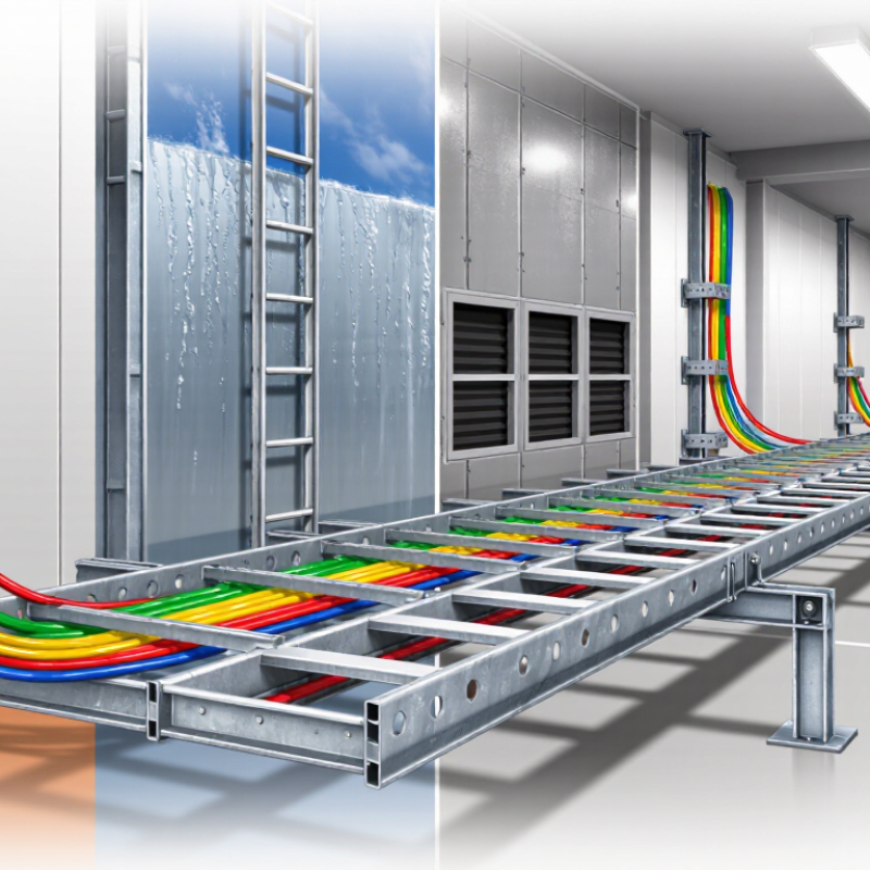
Cable supports should match the environment, not just the cable weight. ISO 12944 corrosivity classes provide a practical starting point. C1 covers very low indoor exposure, while C2 and C3 suit cleaner indoor or moderate outdoor conditions. C4 and C5 indicate more aggressive industrial, coastal, or humid environments. CX may apply to offshore and extreme marine exposure.

One detail is easy to miss. The class alone cannot describe every installation. Record humidity, salt deposits, chemical vapors, ultraviolet exposure, temperature changes, and wet-dry cycles. A sheltered coastal plant may experience less corrosion than an exposed inland process area. Drainage also matters. Trapped water under supports can accelerate damage, even when the selected material appears suitable.

Hot-dip galvanized steel can serve many moderate environments when coating thickness and surface preparation are controlled. Stainless steel may be more appropriate where chlorides remain persistent, but the exact grade requires careful exposure review. Aluminum can reduce weight, though compatibility with adjacent metals must be checked to limit galvanic corrosion. For immersed or frequently splashed areas, use the relevant ISO 12944 immersion categories, not only atmospheric classes.

Field inspections often find problems at cut edges, fasteners, and poorly drained joints. These small details deserve attention. A quick material choice may reduce initial cost, yet create difficult maintenance later. Document the exposure data before approving the support system, and revisit the assessment if process chemicals or site conditions change.